Home » All Products » Controllers » SLC-220/MULTI Smart Leakwise Controller
The SLC-220/MULTI Smart LEAKWISE Controller is a digital signal processor that interfaces with up to four LEAKWISE ID-220 series sensors, providing hydrocarbon spill/leak alerts, including layer buildup and thickness indication. Alerts are transmitted via a variety of outputs and communication interfaces for local or remote reporting.
The SLC-220/MULTI’s modular design and flexible configuration offer solutions for specific customer needs. It can be AC or DC line or battery powered and can operate in wired and/or wireless applications.
Designed for low-power consumption, the SLC-220/MULTI powers on each monitored sensor briefly for sampling and decision-making before turning it off.
All settings and calibration parameters can be adjusted locally or remotely through:
When equipped with a cellular modem, the SLC-220/MULTI can report to multiple remote locations by sending text messages to up to six cell phone recipients and up to two remote modems. An SLR-220 can be one of the messages recipients. The SLR-220 receives and processes data from one or more remote SLC-220 Controllers for up to four remote sensors, and then reports to the central control room SCADA via Modbus, dry contacts, or 4-20mA output. SLC-220 verifies timely reporting from all remote sensors, providing information such as sensor name, status and signal value.
The SLC-220/N4/LI/RL-420/COM/MULTI configuration includes:
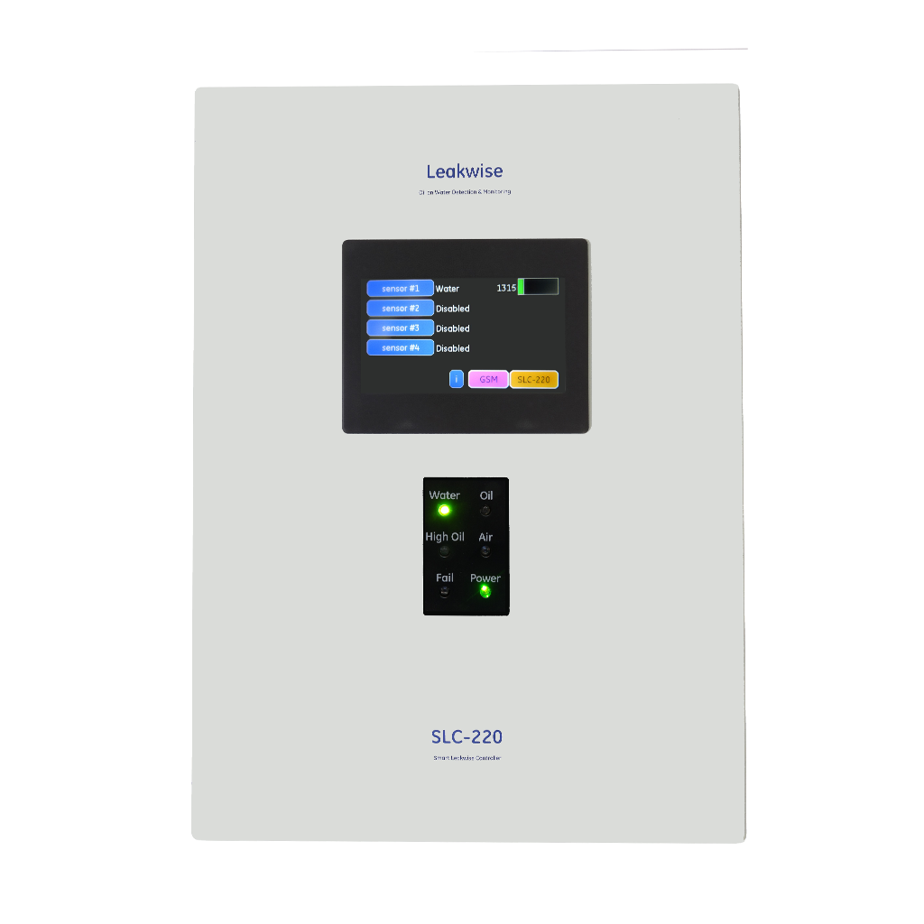
The SLC-220/MULTI Smart Leakwise Controller is a digital signal processor for full support of up to four LEAKWISE ID-220 Series Sensors.
Suitable for diverse industrial applications, the SLC-220/MULTI, together with a LEAKWISE sensor, offers advanced monitoring and flexible integration for reliable hydrocarbon leak detection, monitoring and reporting.
Sensor Support:
Full support up to four LEAKWISE ID-220 series sensors.
Measurement Resolution: 0.1% of sensor’s output signal
Status Lights: Two configurable options:
Display (Optional): LCD display installed on the front panel: 4.3” color LCD, 480 x 272 resolution, with backlight and touch operation. Password protected. For configuration and calibration parameters setting and system status continuous viewing.
Serial Ports: Three serial communication ports
Outputs Board: Up to four boards can be installed. One Outputs Board is supplied inside each controller, up to three additional boards are optional. Each Outputs Board includes:
Note: Each board can be set up to serve four sensors. The relays will indicate Oil / High Oil for sensor 1, Oil / High Oil for sensor 2, etc., and the Fail relay will be common to all sensors.
Operation & Diagnostic: Built-in test for sensors and system diagnostics. SIL 2 verified
Firmware: Main Board firmware upgradeable through the PC RS-232 serial port.
Cellular Modem: Optional, LTE network compatible. Cellular modem and omnidirectional antenna to enable wireless remote reporting and setting to/from up to six cellular phones and two remote modems. SIM card supplied by user.
Installation Distance: Maximum distance to LEAKWISE ID-220 series sensors is 1,200m (4000 ft.), subject to hazardous area restrictions and use of Zener Safety Barriers. Two sets of Zener Safety Barriers can be installed in all enclosure types.
Power Supply: Three options for system power supply
Power Consumption: 11.5W maximum, not including an optional cellular modem.
Enclosure: NEMA 4X (UL for USA and Canada) or IP65, for non-hazardous areas. (other enclosure options are available, see Enclosures & options)
Dimensions: 297 x 297 x 191 mm (11.69 x 11.69 x 7.52 in) for NEMA 4X / IP65 enclosure
Ambient Temperature:
Humidity: 5 to 95% non-condensing
Power consumption calculation: Low-power consumption when Outputs Boards or LCD are not in use.
Total: 11.5W maximum, not including a cellular modem.
Display: LCD display installed on the front panel: 4.3” color LCD, 480 x 272 resolution, with backlight and touch operation. Password protected. For configuration and calibration parameters setting and system status continuous viewing.
Zener Safety Barriers installed inside the enclosure, in series with sensor cable. Up to four sets of safety barriers can be installed inside SLC-220/MULTI.
LTE network compatible. Cellular modem and omnidirectional antenna to enable wireless remote reporting and setting to/from up to six cellular phones and two remote modems. SIM card supplied by user.
A special version of SLC-220 for interfacing up to four locally wired or remote sensors. A remote sensor is wired to a remote SLC-220/BASIC or SLC-220/MULTI. The SLR-220 and SLC-220 controllers are equipped with cellular modems for communicating the remote sensors to the SLR-220.